
Contenu
The Duraspark II ignition system debuted in 1976 with the intent to make substantial increases in secondary voltage and extend system maintenance intervals. Spark plug gaps were widened to take advantage of the heightened current and to prolong spark plug life. Special testers were devised at the time, but the troubleshooting capabilities of such analyzers are easily duplicated with an accurate volt-ohmmeter. Knowing what values to look for in certain circuits is often the only specific information needed for effective system diagnosis.
Step 1
Test the car battery state of charge and clean the cable terminals if necessary. Charge the battery if stored voltage is below 12.5 volts. Replace the battery if voltage drops below 9 volts while cranking the engine. Ensure battery and cable conditions are good before evaluating any subsequent voltage readings.
Step 2
Measure the voltage to the ignition coil positive terminal while cranking the engine. Repair the circuit from the ignition switch, or replace the switch if the reading is not the same as battery cranking voltage. Turn off the power to the ignition system and measure the resistance of the ignition coil primary terminals. Replace the coil if this reading exceeds 3 ohms.
Step 3
Test the resistance of the distributor pickup coil with the ignition switch remaining in the "Off" position. Unplug the distributor wire harness from the black plastic connector. Measure the resistance between the two parallel prongs of the distributor harness. Replace the pickup coil if the resistance is more than 850 ohms or less than this value by 60 ohms or more. Measure the resistance between both parallel prongs and the single perpendicular prong, one at a time. Replace the pickup coil if any value below 70,000 ohms is displayed.
Step 4
Restore the connection at the distributor harness. Measure the cranking voltage to the ignition module, or "brain-box". Probe the white wire leading into the module while cranking the engine. Inspect the circuit from the starter solenoid "S" terminal, if the voltage is weak or missing entirely. Replace the solenoid if no faults are found in the circuit.
Probe the red wire leading to the ignition module with the ignition switch in the "Run" position to ensure a proper voltage signal. Repair the circuit if readings are less than battery voltage. Test the resistance of the ground circuit by probing the black wire at the module and distributor. repair this circuit if readings exceed 0.3 ohms. Replace the module if symptoms persist without any other ignition system causes.
Tip
- Perform the pickup coil tests at operating temperatures, or after an engine stall occurs, as temperature sensitivity from this component is a common cause of stalling. Dismount the ignition module to inspect the underside. Replace the module if the rubbery insulation is loose, droopy or missing.
Warning
- Keep well clear of moving parts, such as cooling fans, while working on a running engine. Avoid contact with spark plug wires of running vehicles. The high voltage in these circuits can interrupt heart functions.
Items you will need
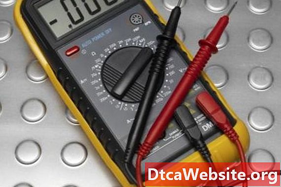
- Variable range volt-ohmmeter


